In the world of gas fireplaces, efficiency, aesthetics, and functionality play pivotal roles in delivering a truly enchanting ambiance. If you’re a gasfitter encountering fireplaces by Real Fires that have fallen into disuse or disrepair, this blog post is tailored just for you. We delve into the art of rekindling the allure of these neglected hearths by replacing outdated Real Fires burners with the innovative and efficient Living Flame burner units.
Join us on a journey that not only revitalizes home fireplaces but also provides step-by-step instructions for a seamless installation process. From decommissioning non-functional fire elements to embracing the radiance of Living Flame technology, this guide equips you with the knowledge to breathe new life into every hearth you touch.
Please note that the following installation instructions are essential for the proper installation of Real Fires Inserts. It is crucial to follow these guidelines carefully to ensure a safe and effective installation process.
Installation and Commissioning Instructions
For gasfitters: Living Flame Burner Installation instructions
. . . . .
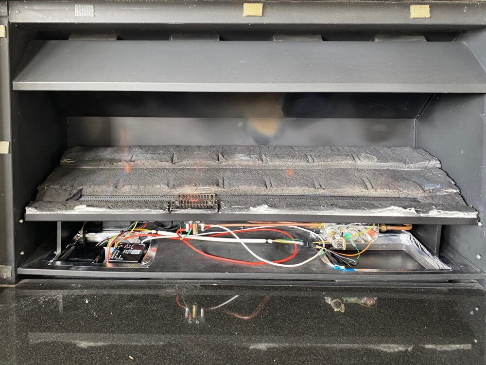
Image 1: To be replaced – Old Real Fires Burner
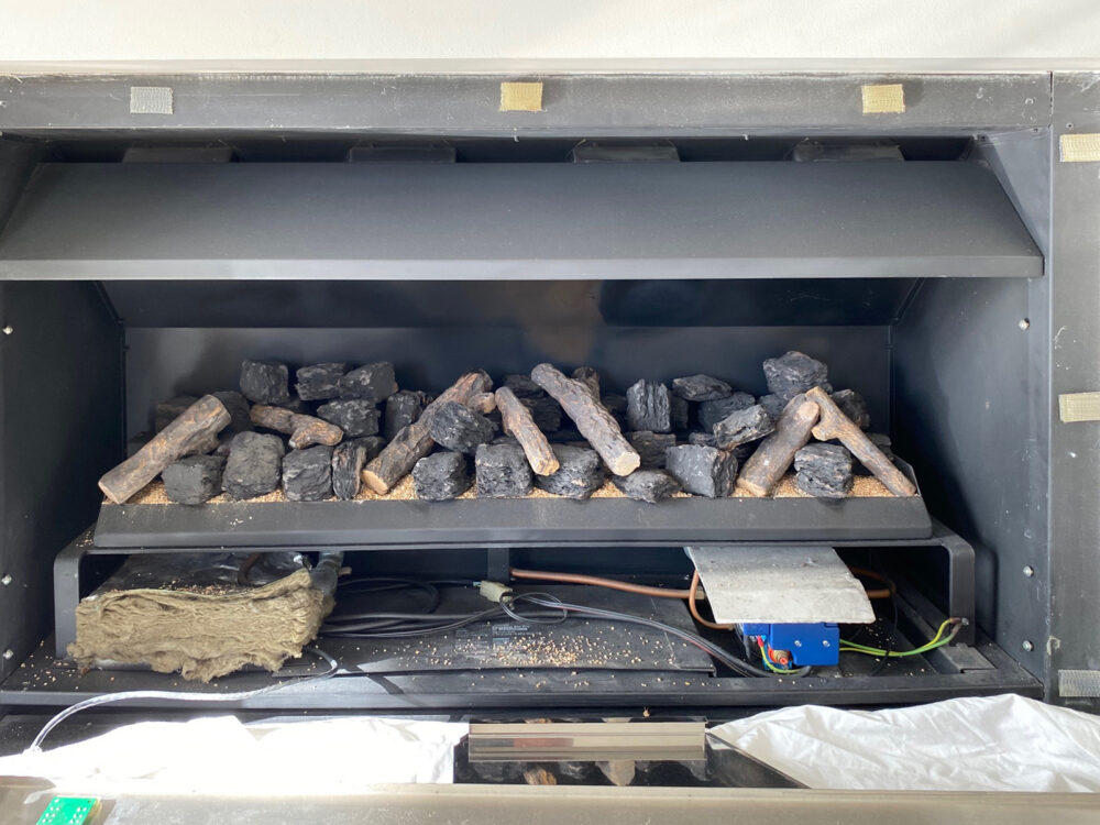
1. Isolate power and gas from existing fireplace.
2. Remove the burner and controls, leaving the pipework and black power feed intact.
3. Cut the power cable close to the existing plug. Attach the supplied male plug / female pins to the existing 3-core cable (refer to Image 2).
. . . . .
Image 2: Male Plug / Female Pins
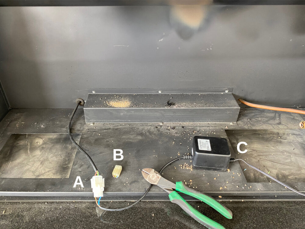
A – New Plug
B – Old Plug
C – Transformer
. . . . .
4. Fit steel inserts into left and right base cavities. Duct tape around edges to form a seal (refer to Image 3).
. . . . .
Image 3: Steel Inserts Fitted and Sealed
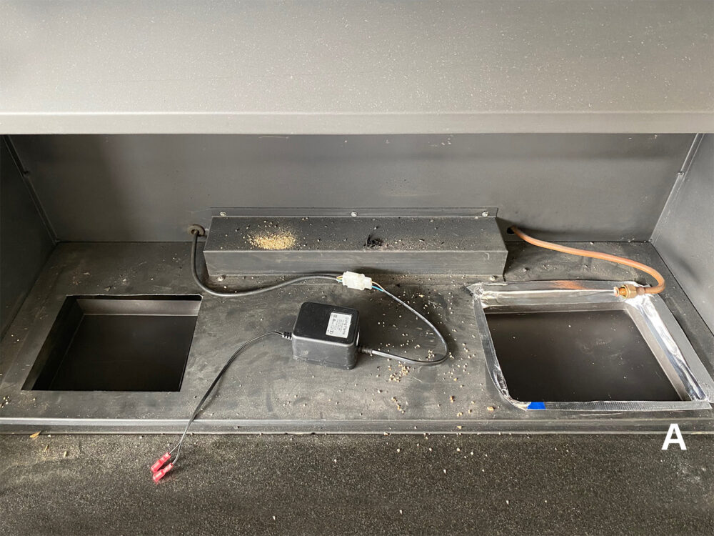
A – Duct tape forms sealed edge
. . . . .
5. Connect the female transformer plug to the male power cable.
6. Plug the transformer into the control pack and position into the left base cavity.
7. Position the burner and connect the 3/8” flare nut to the burner.
8. Then, connect the color-coded electrical connections and the yellow / green earth connection from the control pack to the gas valve.
9. Connect the Red (spark) HT Lead and the White (flame) HT Lead to the pilot terminals (refer to Image 4).
. . . . .
Image 4: Electronic Pilot Assembly
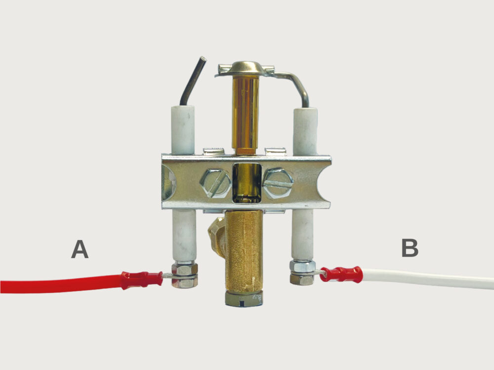
A – Red (Spark) HT Lead
B – White (Flame) HT Lead
. . . . .
10. The Living Flame Real Fires burner insert should now be fitted into position (refer to Image 5).
. . . . .
Image 5: The Living Flame Real Fires burner fitted into position
. . . . .
11. Reconnect the gas supply and perform a gas check on the flare nut fitting.
12. Re-establish the power supply. You should hear an audible “beep beep” indicating successful connection.
13. Turn on the fireplace using the Remote Control. You should hear an audible “beep beep” confirming activation.
14. The pilot sequence will start, and after purging, the fireplace should ignite.
15. Conduct a gas test on all fittings under the burner.
16. Using the ‘Outgoing’ test point, check the up and down operation of the valve (refer to Image 6).
. . . . .
Image 6: ProFlame Gas Valve
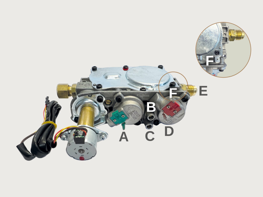
A – Colour coded electrical connection #1
B – Incoming test point (top)
C – Outgoing test point (below)
D – Colour coded electrical connection #2
E- 3/8″ Flare
F – Yellow / Green earth connection (on top)
. . . . .
For gasfitters: Commissioning an Ember Layout
Commissioning the fireplace is a necessary procedure to guarantee compliance with safety standards, and the manufacturer’s installation and operation instructions. This mandatory process ensures proper functioning of the flue, fireplace, and room ventilation. By conducting a thorough commissioning, you can ensure the safety and efficiency of the gas fireplace while meeting all necessary requirements and guidelines.
. . . . .
Image 7: Commissioning: Ember Layout
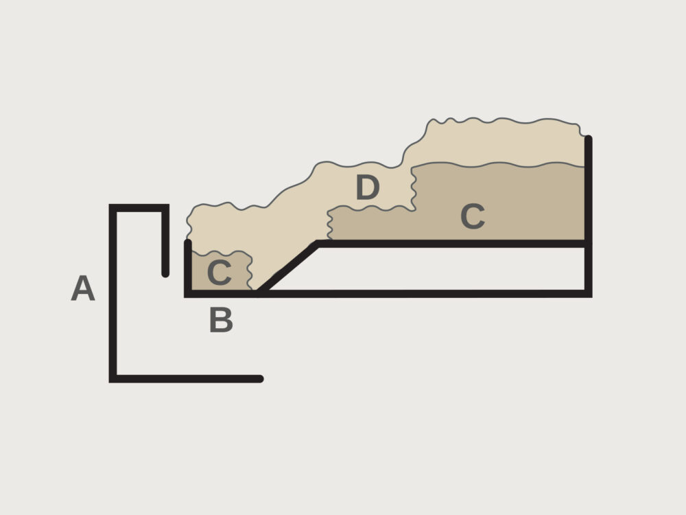
A – Removeable front
B – ST / ST Burner base
C – Ceramic blanket
D – Embers
. . . . .
1. Spread Embers:
• Spread the embers evenly across the burner top, ensuring the port holes section is loosely filled.
2. Placing the Log Set:
• Carefully position the log set into the ember bed, ensuring that the wires of the log frame are concealed.
3. Fire Observation:
• Start the burner and observe the fire for a minimum of 30 minutes.
• Pay close attention to the flame picture and heat output to ensure proper functioning.
• Smoke test to check the chimney function using replacement burner.
4. Initial Operation:
• When initially operating the fireplace, it is recommended to run it for at least 4 hours.
• This helps burn off any residual smells and allows the paints to harden effectively.
. . . . .
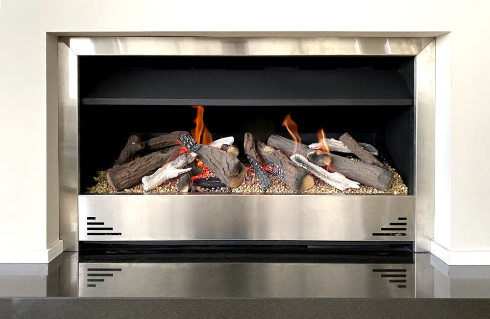
Making the switch seamless is our priority. Contact us for more information and ensure a smooth transition to Living Flame burners.